
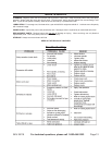
3.3
Owner's of the Harbor Freight Tools Drill 38119 gave it a score of 3.3 out of 5. Here's how the scores stacked up:

Page 7SKU 38119 For technical questions, please call 1-800-444-3353.
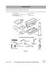
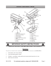
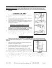
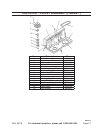
Slide the Table Support with Table over the Column (#11) and secure at a convenient position by 2.
tightening the Table Support Locking Handle.
Head to Column
It may be necessary to unscrew the Head Lock Set Screws (#3) slightly to ensure they do not pro-1.
trude internally, as this will prevent the head from sliding fully into position.
With assistance, raise the Head and place it on top of the Column, ensuring it slides home fully.2.
Align the head with the base (#7), and rmly secure with the Head Lock Set Screws (#3).3.
Screw the three Feed Handles (#15) rmly into the hub of the Feed Shaft.4.
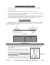
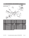
Installing the Chuck
With the Chuck Guard lifted clear of the spindle nose, slide the work table up the column to within 1.
6” of the spindle.
Open the jaws of the chuck to their maximum, using the Chuck Key supplied.2.
Put a piece of scrap wood on the table to protect the Chuck Nose.3.
Ensuring all parts are thoroughly clean and dry and burr free, place the chuck over the end of the 4.
spindle, and pull the spindle down using the feed handles, pressing the chuck jaws hard against the
piece of scrap wood until the chuck is forced home.
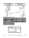
Pulley Cover Knob
Locate the knob with pan head screw and attach to the cover. 1.
Screw on tightly.2.
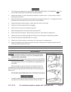
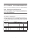
Adjusting the Drive Belt
The drive belt is pre-installed. However, if the belt requires tightening or the spindle speed needs to
be changed, proceed with the following steps:
Undo the Belt Tension Locking Screw to loosen the belt.1.
Consult the chart inside the pulley cover (or the Drill Speed chart in this manual), and install the belt 2.
in the position corresponding to spindle/drill speed required.
Lever the motor, on its bracket, away from the head, so that tension is applied to the belt. Tension 3.
is correct when the belt deects by approximately 1/2” at its center when using reasonable thumb
pressure. Lock the motor in this position using the locking screw.
Note: If the belt slips during operation, adjust the belt tension.
REV 01b


Find Your Products By Category
- Home Audio
- Computer Equipment
- Photography
- TV and Video
- Household Appliance
- Communications
- Car Audio and Video
- Automotive
- Cell Phone
- Portable Media
- Kitchen Appliance
- Fitness & Sports
- Lawn and Garden
- Musical Instruments & Equipment
- Power Tools
- Personal Care
- Marine Equipment
- Video Game
- Baby
- Laundry Appliance
- Outdoor Cooking
Please Login
